المنتجات الساخنة

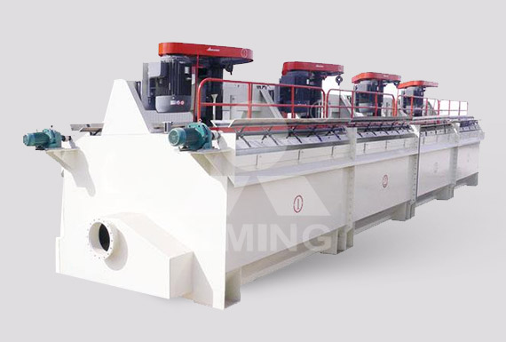
Dorr-Oliver Eimco Flotation Technology
2017-10-2 Cell Technology with the Greatest Installed Capacity of any Flotation Manufacturer Dorr-Oliver Eimco pioneered the way for large cell technology. From its first Wemco 257m3 cell installed in 2003, to now even bigger 300m3 cells being installed in Chile. These 26 x 300m3 Wemco cells will be the first major installation of 300’s for
Contact
Model for the Design and Control of Flotation Plants
2010-10-2 flotation cell complicate tile formulation of a reliable modeL for flotation kinetics. The need for such modeLs for both the design and control of operating plants is w~U established, and much useful progress has been made. The analogy between the flotation process and a chemical reaction. which until
Contact
DETERMINATION OF TURBULENCE AND UPPER SIZE
2012-8-1 flotation cells to elucidate complexity of the hydrodynamic characteristics of cells, has been used in flotation science by Koh et al. (2000), Koh and Schwarz (2003 and 2006), Lane et al. (2002), Liu and Schwarz (2009), Sahbaz (2010) etc. In CFD modelling, a flotation cell is discretized into particular finite volumes where local values of flow
Contact
OTC 17612 Compact Induced Gas Flotation as an
2012-6-5 flotation cell 2. Uniform distribution of gas bubbles throughout the flotation cell 3. Minimizing the size of the gas bubbles 4. Maximizing the size of the contaminants to be removed 5. Maximizing the tendency of the contaminants to remain in contact with rising gas bubbles Vessel Hydraulics. The first points are related to flotation cell
Contact
Up-scaling of froth flotation equipment
2015-8-31 Mixing zone: Zone around the impeller of the flotation cell, in the test work of this research located in the cell bottom. Quiescent zone: Laminar flow zone of pulp between the mixing and froth zones of the flotation cell, through which loaded bubbles rise to the top of the cell. Responses: Test results being compared in a factorial design test.
Contact
A STUDY OF CLEANER FLOTATION IN AITIK Oulu
The goal of this thesis is to give the reader a good idea how a flotation cell operates, especially those in Aitik cleaner process. At the same it is a good opportunity for the author to get a good comprehension how flotation works inside a flotation cell. The author would like to thank Boliden Mineral for the opportunity to let him do the
Contact
Capacity and Flotation for Recreational Boats
2019-3-22 Capacity and Flotation for Recreational Boats. FOREWORD In 2018 The U. S. Coast Guard replaced Table 4 (the table of outboard engine weights) with the ABYC tables from ABYC Standard S30 now in 33 CFR 183.75. The old Table 4 had not been updated since 1983. The ABYC table is updated every five years.
Contact
CommonBasic Formulas for Mineral Processing
2016-3-20 N—Number of cells required. T—Contact time in minutes. C—Volume of each cell in cu. ft. Long Tons of Solids: N = W x T/40 x C (R/L + 1/S) Short Tons of Solids: N = W x T/45 x C (R/L + 1/S) In the above formulas, no allowance is
Contact
CFD MODELS OF MICROCEL AND JAMESON FLOTATION
2009-10-30 CFD model incorporates micro-processes from cell hydrodynamics that affect particle-bubble attachments and detachments. The issues facing coal flotation are two-fold: firstly, a drive to increase capacity of existing installations, and secondly, a need to increase the recovery of coarse coal. These issues are influenced by the flow conditions
Contact
NOVEL VERTICAL COLUMN FLOTATION DESIGN FOR
2012-6-5 flotation cell, the team decided to conduct physical laboratory tests to verify the CFD results. The test vessel measures 60“OD X 14’ S/S. A conventional gas eductor used successfully in horizontal flotation cells was purchased and installed in the normal fashion inside the vessel. Figure 3 shows the fact that the gas bubbles entering the
Contact
Calculation of the Flotation Rate Constant of Chalcopyrite
The flotation recovery of chalcopyrite particles in a complex sulfide ore was measured in a Rushton turbine flotation cell as a function of particle size.
Contact
A computational fluid dynamics model for the flotation
The fundamental flotation model due to Pyke for the flotation rate constant (Pyke, 2004) was used as the basis for the incorporation of the transient CFD data for the computation of micro-and
Contact
CFD SIMULATION OF GAS-LIQUID FLOW IN A LARGE
2009-10-28 The largest flotation cell which has been used in plant has an effective capacity of 200 m3. And the KYF-320 flotation cell whose size is 320 m3 has been examined through the industrial tests in 2008. Figure 1 gives a picture of the development of BGRIMM large flotation cell sizes. One important development area of the recent decade has been
Contact
Model for the Design and Control of Flotation Plants
2010-10-2 flotation cell complicate tile formulation of a reliable modeL for flotation kinetics. The need for such modeLs for both the design and control of operating plants is w~U established, and much useful progress has been made. The analogy between the flotation process and a chemical reaction. which until
Contact
Capacity and Flotation for Recreational Boats
2019-3-22 Capacity and Flotation for Recreational Boats. FOREWORD In 2018 The U. S. Coast Guard replaced Table 4 (the table of outboard engine weights) with the ABYC tables from ABYC Standard S30 now in 33 CFR 183.75. The old Table 4 had not been updated since 1983. The ABYC table is updated every five years.
Contact
CFD MODELS OF MICROCEL AND JAMESON FLOTATION
2009-10-30 CFD model incorporates micro-processes from cell hydrodynamics that affect particle-bubble attachments and detachments. The issues facing coal flotation are two-fold: firstly, a drive to increase capacity of existing installations, and secondly, a need to increase the recovery of coarse coal. These issues are influenced by the flow conditions
Contact
OTC 17612 Compact Induced Gas Flotation as an
2012-6-5 flotation cell 2. Uniform distribution of gas bubbles throughout the flotation cell 3. Minimizing the size of the gas bubbles 4. Maximizing the size of the contaminants to be removed 5. Maximizing the tendency of the contaminants to remain in contact with rising gas bubbles Vessel Hydraulics. The first points are related to flotation cell
Contact
NOVEL VERTICAL COLUMN FLOTATION DESIGN FOR
2012-6-5 flotation cell, the team decided to conduct physical laboratory tests to verify the CFD results. The test vessel measures 60“OD X 14’ S/S. A conventional gas eductor used successfully in horizontal flotation cells was purchased and installed in the normal fashion inside the vessel. Figure 3 shows the fact that the gas bubbles entering the
Contact
Hydrodynamics of froth flotation and its effects on fine
2021-11-1 Froth flotation is a physicochemical separation technique that exploits the difference in the surface wettability of mineral particles (Wills and Finch, 2016).From a heterogeneous mixture of solids, hydrophobic particles are made to attach to gas bubbles and subsequently carried to the froth phase and recovered as a froth product (typically the value mineral
Contact
Fluid Flow and Kinetic Modelling in Flotation Related
2022-2-1 The kinetic modelling of flotation process has been reviewed in detail in three major flotation equipment namely mechanically agitated flotation cell,
Contact
A computational fluid dynamics model for the flotation
The fundamental flotation model due to Pyke for the flotation rate constant (Pyke, 2004) was used as the basis for the incorporation of the transient CFD data for the computation of micro-and
Contact
Recent advances in computational fluid dynamics
Flotation process is a multi‐phase and multi‐scale complex flow system, in which hydrodynamics plays an indispensable role. In recent years, computational fluid dynamics (CFD) numerical
Contact
CFD SIMULATION OF GAS-LIQUID FLOW IN A LARGE
2009-10-28 The largest flotation cell which has been used in plant has an effective capacity of 200 m3. And the KYF-320 flotation cell whose size is 320 m3 has been examined through the industrial tests in 2008. Figure 1 gives a picture of the development of BGRIMM large flotation cell sizes. One important development area of the recent decade has been
Contact
Characterisation Measurements in Industrial Flotation Cells
2018-2-20 than installed motor capacity. This suggests all three mills had sufficient power capacity for additional throughput. Ball Mill 1 Cyclones 1 Sump 1 BM 1 Cyc H2O BM 1 H2O Ball Mill 2 Cyclones 2 Sump 2 BM 2 H2O Sump 1 Prod 3573.115 62.000 3306.572 0.429 Cyclones 1 U/F 2412.615 74.797 1566.889 0.672 Ball Mill 1 Prod 2412.615 74.797 1566.889
Contact
Model for the Design and Control of Flotation Plants
2010-10-2 Model for the Design and Control of Flotation Plants By R. P. KING, n .Se. (Eog.), M.Se. {Ea&.}, Ph.D .. PI'. Eog. SYNOPSIS A model of the flotation process can be used effectively for dc.9ign and control. For ~iSQ purposes it can be used to predict the performance of a large plant from laboratory and pilot plant data. 11 can be used for control
Contact
Capacity and Flotation for Recreational Boats
2019-3-22 Capacity and Flotation for Recreational Boats. FOREWORD In 2018 The U. S. Coast Guard replaced Table 4 (the table of outboard engine weights) with the ABYC tables from ABYC Standard S30 now in 33 CFR 183.75. The old Table 4 had not been updated since 1983. The ABYC table is updated every five years.
Contact
Fluid Flow and Kinetic Modelling in Flotation Related
2022-2-1 The kinetic modelling of flotation process has been reviewed in detail in three major flotation equipment namely mechanically agitated flotation cell,
Contact
A STUDY OF CLEANER FLOTATION IN AITIK Oulu
The goal of this thesis is to give the reader a good idea how a flotation cell operates, especially those in Aitik cleaner process. At the same it is a good opportunity for the author to get a good comprehension how flotation works inside a flotation cell. The author would like to thank Boliden Mineral for the opportunity to let him do the
Contact
Dissolved Air Flotation Design Calculations Spreadsheet
An example dissolved air flotation design calculations spreadsheet is partially shown in the image below. This Excel spreadsheet can be used to calculate A/S, the needed air to solids ratio, and the required DAF area based on user input
Contact
TECHNICAL PAPER Induced Gas Flotation (IGF) within an
2018-3-21 Induced Gas Flotation (IGF) and Induced Static Flotation (ISF) units provide a more enhanced approach to oil removal through the addition of gas bubbles to aid in the flotation of oil to the surface. Gas, which is typically induced by sparging tubes or eductors, floats the oil to the surface, which can then be skimmed off. In addition
Contact